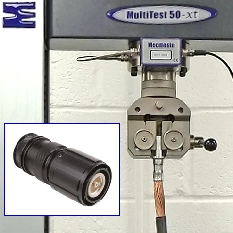
Solar panel peel testing


Solution
- Repeatable semi-automated testing to international standards
- Data collection to quantify results and compare samples
- Multiple tests of all component composite module layers on one machine
Benefits
- Software-controlled tensile tester
- Pinch grips designed for thin sheet and foil specimens
- Peel table fixture for 90 degree tests
Requirement
A solar module, also called a PV or photovoltaic module and solar panel, is subjected to extreme conditions of temperature, ultraviolet radiation, rain, ice and wind throughout the year. Over its expected lifetime it needs to withstand these conditions without suffering a significant degradation in electrical or mechanical performance. In the PV panel industry, there are a number of tests conducted to verify the mechanical strength of materials and jointed components in these multi-layered laminate products. One of the most significant is the peel test.
Peel testing is used to qualify the adhesion of interconnection ribbons onto solar cell metallizations. A typical cell interconnection peel test specimen comprises narrow copper-coated ribbons adhered to the crystalline silicon cell substrate itself.
The measured peel forces and the fracture patterns serve as quality criteria to accept or reject a cell type for integration to a module, to validate a new metallization paste formulation or a conductive glue and to adjust manufacturing processes, such as paste printing/firing or soldering in a tabber-stringer machine.
Other peel tests include the characterisation of the laminate material interface in PV modules, which form protection against water corrosion and UV radiation. This is highly significant since any debonding can introduce pathways for corrosion and oxidation, ultimately degrading module efficiency.
The front glass and the back sheet of the module provide a rigid support from which an encapsulating polymer layer (EVA) is peeled off. Test methods in standards ASTM D6862-11 and EN 28510-1 both cover ’90 degree Peel Resistance of Adhesives’ and are regularly used in this context.
Solution
Using a motorised tensile tester (Mecmesin MultiTest or later OmniTest UTM) fitted with a correctly-rated loadcell, grips designed to hold a thin material sample and software capable of producing a peel graph; the joint is peeled according to the appropriate standard method.
Peel tests within this industry are conducted at various test speeds and constant peel angles of 45°, 90°, 135° and 180°. It should be noted that results may vary significantly depending on these factors, which must be considered in sample comparisons. Data acquisition software greatly enhances the ability to analyse results. The widely-adopted test standards EN 50461 and IEC 61730-2 stipulate a test speed of 50 mm/min and 90° peel angle with an acceptable minimum peel criteria for the soldered/glued ribbon of 1 N/mm width.
The software environment enables the manufacturer to create a library of peel test routines to perform specific adhesion tests on the substrates of the constituent laminated sub-elements. Repeatable testing can then be performed easily and confidently by changing the grips, if necessary, then recalling and running the appropriate routine.
Test equipment
- OmniTest/MultiTest 2.5 software-controlled tensile test system
- Emperor Force software, replaced by VectorPro
- Pinch grips
- Fixtures to hold test specimens


